PCB Assembly & First Boot
The Satellite1 Dev Kit comes in two pieces:
- The "Hat" (round board)
- The "Core" (rectangular board)
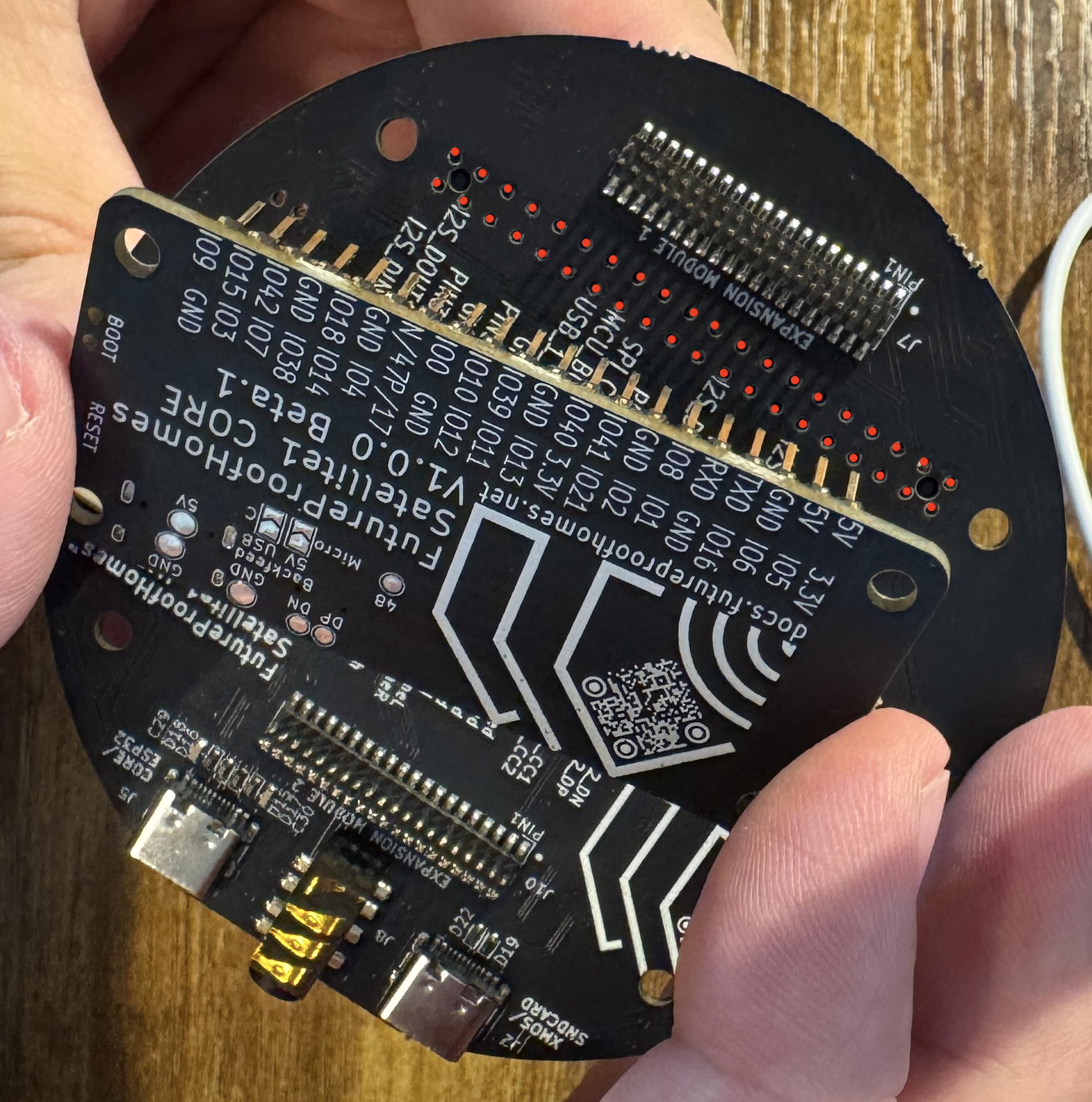
You'll notice a standard Raspberry Pi 40-pin header on the Hat board (marked in red). Carefully align the Core board's 2 rows of pins with the Hat's 40 pin connector and press them together.
Press Firmly!
The 40-pin should poke through the top of the HAT so that it feels like reading braille with your fingers.
FUN FACT!
By design you can mount the Satellite1 Hat board to a Raspberry Pi Zero 2W. And yes, we're working on RPI firmware. :) If you're a serious developer and want to help please find us in the Discord community.
First Boot - Powering On
-
Plug-in to the Hat's USB-C port labeled "CORE/ESP" using the 30W USB-C power adapter & cable supplied in your dev kit.
-
Use correct USB-C port
If you plug-in to the "XMOS" port you will not hear audio from the Sat1's amplifier to your speaker.
-
-
Upon first boot, you will see a blue LEDs count down clockwise as the device flashes the XMOS audio processor.
-
Finally, the LEDs will begin to sparkle a warm white color. Congratulations! Click here to connect your Satellite1 to Home Assistant.